Asus V3-M2V890 Bedienungsanleitung
Stöbern Sie online oder laden Sie Bedienungsanleitung nach Computers Asus V3-M2V890 herunter. Asus V3-M2V890 User Manual Benutzerhandbuch
- Seite / 90
- Inhaltsverzeichnis
- LESEZEICHEN
Bewertet. / 5. Basierend auf Kundenbewertungen
- V-Series M2V890 1
- First Edition V1 2
- September 2006 2
- Table of contents 3
- Safety information 7
- About this guide 8
- System package contents 10
- System introduction 11
- 1.1 Welcome! 12
- 1.2 Front panel 12
- 1-3ASUS V-Series M2V890 13
- 1.3 Rear panel 14
- 1-5ASUS V-Series M2V890 15
- Voltage selector 16
- 1.4 Internal components 17
- Basic installation 19
- 2.1 Preparation 20
- 2.2 Before you proceed 20
- panel assembly 21
- 2.4.1 Overview 22
- 2.4.2 Installing CPU 22
- Gold triangle 23
- Small triangle 23
- Retention Module Base 24
- CPU Heatsink 24
- 2.5 Installing a DIMM 26
- Qualified Vendors Lists (QVL) 27
- 2.5.3 Removing a DDR2 DIMM 28
- 2.5.2 Installing a DDR2 DIMM 28
- 2.6 Expansion slots 29
- 2.6.4 PCI slots 31
- 2.6.3 PCI Express x1 slot 31
- 2.6.5 PCI Express x16 slot 31
- IDE ribbon cable 32
- Power cable 32
- 2-15ASUS V-Series M2V890 33
- Serial ATA cable 34
- Serial ATA power 34
- Floppy ribbon 36
- and side cover 37
- Starting up 39
- 3.2 Powering up 40
- 3.3 Support CD information 41
- 3.3.2 Drivers menu 42
- 3.3.3 Utilities menu 43
- 3.3.4 Make Disk menu 44
- 3-7ASUS V-Series M2V890 45
- 3-8 Chapter 3: Starting up 46
- Motherboard information 47
- 4.1 Introduction 48
- 4.2 Motherboard layout 48
- (Default) 49
- Clear CMOS 49
- 4.4 Connectors 50
- NOTE:Orient the red markings 52
- (usually zigzag) on the IDE 52
- CPU FAN PWM 53
- CPU FAN IN 53
- CPU FAN PWR 53
- 4-9ASUS V-Series M2V890 55
- Analog front panel connector 55
- COM port connector 55
- System panel connector 56
- Right Audio Channel 57
- Left Audio Channel 57
- BIOS setup 59
- DOS environment 60
- XP environment 60
- 5.1.2 ASUS EZ Flash utility 61
- 5.1.3 AFUDOS utility 62
- Updating the BIOS file 63
- 5.1.4 ASUS Update utility 64
- 5-7ASUS V-Series M2V890 65
- 5-8 Chapter 5: BIOS setup 66
- 5.2 BIOS setup program 67
- 5.2.2 Menu bar 68
- 5.2.1 BIOS menu screen 68
- 5.2.3 Navigation keys 68
- 5-11ASUS V-Series M2V890 69
- 5.3 Main menu 70
- Type [Auto] 71
- LBA/Large Mode [Auto] 71
- 5.3.5 System Information 72
- 5.4 Advanced menu 73
- Legacy USB Support [Enabled] 74
- BIOS EHCI Hand-Off [Enabled] 74
- 5.4.2 CPU Configuration 74
- 5.4.3 Chipset 75
- NorthBridge C o nfiguration 75
- Memory Config u ration 75
- ECC Conguration 76
- DRAM ECC Enable [Enabled] 76
- 4-Bit ECC Mode [Disabled] 76
- DRAM BG Srub [Disabled] 76
- Power Down Control [Auto] 77
- Alternate VID [0.850V] 77
- Hyper Transport AGP 78
- Serial Port1 Mode [Normal] 79
- Serial Port2 Mode [Normal] 79
- 5.4.5 PCI PnP 80
- Plug and Play O/S [No] 81
- PCI Latency Timer [64] 81
- Allocate IRQ to PCI VGA [Yes] 81
- Palette Snooping [Disabled] 81
- IRQ xx [Available] 81
- 5.5 Power menu 82
- 5.5.5 Hardware Monitor 84
- 5.6 Boot menu 85
- Quick Boot [Enabled] 86
- Full Screen Logo [Enabled] 86
- Bootup Num-Lock [On] 86
- 5.6.3 Security 87
- Change User Password 88
- 5.7 Exit menu 89
- Exit & Discard Changes 90
- Discard Changes 90
- Load Setup Defaults 90
Inhaltsverzeichnis
Seite 1 - V-Series M2V890
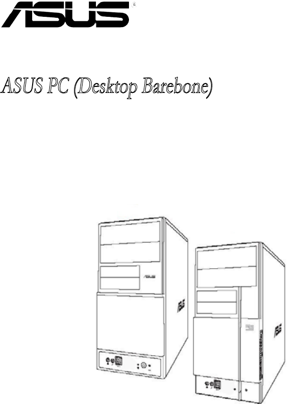
V-Series M2V890ASUS PC (Desktop Barebone)
Seite 2 - September 2006
xSystem package contentsCheck your ASUS V-Series M2V890 barebone system package for the following items.If any of the items is damaged or missing, con
Seite 3 - Table of contents
Chapter 1System introductionThis chapter gives a general description of the ASUS V-Series M2V890 Barebone System. The chapter lists the system feature
Seite 4
1-2 Chapter 1: System introduction1.1 Welcome!Thank you for choosing the ASUS V-Series M2V890!The ASUS V-Series M2V890 is an all-in-one barebone syst
Seite 5
1-3ASUS V-Series M2V8901. 5.25-inch drive bay covers. These bays are for IDE optical drives.2. 3.5-inch drive bay covers. These slots are for 3.5-in
Seite 6
1-4 Chapter 1: System introduction1.3 Rear panelThe system rear panel includes the power connector and several I/O ports that allow convenient connec
Seite 7 - Safety information
1-5ASUS V-Series M2V8905. COM port. This 15-pin port is for a VGA monitor or other VGA-compatible devices.6. Parallel port. This 25-pin port connect
Seite 8 - About this guide
1-6 Chapter 1: System introductionVoltage selectorThe system’s power supply unit has a 115 V/230 V voltage selector switch located beside the power co
Seite 9
1-7ASUS V-Series M2V8901.4 Internal componentsThe illustration below is the internal view of the system when you remove the top cover and the power s
Seite 10 - System package contents
1-8 Chapter 1: System introduction
Seite 11 - System introduction
Chapter 2Basic installationThis chapter provides step-by-step instructions on how to install components in the system.
Seite 12 - 1.2 Front panel
iiCopyright © 2006 ASUSTeK COMPUTER INC. All Rights Reserved.No part of this manual, including the products and software described in it, may be repro
Seite 13 - 1-3ASUS V-Series M2V890
2-2 Chapter 2: Basic installation 2.1 PreparationBefore you proceed, make sure that you have all the components you plan to install in the system.Bas
Seite 14 - 1.3 Rear panel
2-3ASUS V-Series M2V8902.3 Removing the side cover and front panel assembly1. Remove the cover screws on the rear panel.2. Pull the side cover
Seite 15 - 1-5ASUS V-Series M2V890
2-4 Chapter 2: Basic installation 2.4 Central Processing Unit (CPU)2.4.1 OverviewThe motherboard comes with a 940-pin AM2 socket designed for the AM
Seite 16 - Voltage selector
2-5ASUS V-Series M2V8903. Position the CPU above the socket such that the CPU corner with the gold triangle matches the socket corner with a small t
Seite 17 - 1.4 Internal components
2-6 Chapter 2: Basic installation 2.4.3 Installing the heatsink and fanThe AMD Athlon™ 64 X2/AMD Athlon™ 64/AMD Sempron™ processor require a speciall
Seite 18
2-7ASUS V-Series M2V8902. Attach one end of the retention bracket to the retention module base.3. Align the other end of the retention bracket (nea
Seite 19 - Basic installation
2-8 Chapter 2: Basic installation 2.5 Installing a DIMMThe system motherboard comes with two Double Data Rate 2 (DDR2) Dual Inline Memory Module (DIM
Seite 20 - 2.2 Before you proceed
2-9ASUS V-Series M2V890Qualified Vendors Lists (QVL)DIMM supportSide(s): SS - Single-sided DS - D oub le- sid edVisit the ASUS website for the lat
Seite 21 - panel assembly
2-10 Chapter 2: Basic installation 2.5.3 Removing a DDR2 DIMMFollow these steps to remove a DIMM.1. Simultaneously press the retaining clips outward
Seite 22 - 2.4.2 Installing CPU
2-11ASUS V-Series M2V8902.6 Expansion slotsIn the future, you may need to install expansion cards. The following sub-sections describe the slots and
Seite 23 - Small triangle
iiiTable of contentsNotices ... viSafety information ...
Seite 24 - CPU Heatsink
2-12 Chapter 2: Basic installation * These IRQs are usu all y a vai lab le for IS A o r P CI dev ice s.When using PCI cards on shared slots, ensure
Seite 25
2-13ASUS V-Series M2V8902.6.4 PCI slotsThe PCI slots support cards such as a LAN card, SCSI card, USB card, and other cards that comply with PCI spec
Seite 26 - 2.5 Installing a DIMM
2-14 Chapter 2: Basic installation 2.7 Installing an optical driveRefer to the instructions in this section if you wish to install a new optical driv
Seite 27 - Qualified Vendors Lists (QVL)
2-15ASUS V-Series M2V8902.8 Installing a hard disk driveThe system may have one pre-installed 3.5-inch Serial ATA or IDE hard disk drive. Refer to th
Seite 28 - 2.5.2 Installing a DDR2 DIMM
2-16 Chapter 2: Basic installation If your Serial ATA HDD has both 4-pin and 15-pin connectors at the back, use either the 15-pin SATA power adapter p
Seite 29 - 2.6 Expansion slots
2-17ASUS V-Series M2V890To install an IDE hard disk drive:1. Follow steps 1-4 of the previous section.2. Connect the blue interface of the IDE ribbo
Seite 30
2-18 Chapter 2: Basic installation 2.9 InstallingaoppydiskdriveThe V-Series M2V890 Barebone system comes with one 3.25-inch drive bay for a opp
Seite 31 - 2.6.5 PCI Express x16 slot
2-19ASUS V-Series M2V8902.10 Removing the bay covers and reinstalling the front panel assembly and side coverIf you installed an optical and/or
Seite 32 - Power cable
2-20 Chapter 2: Basic installation
Seite 33 - 2-15ASUS V-Series M2V890
Chapter 3Starting upThis chapter helps you power up the system and install drivers and utilities from the support CD.
Seite 34 - Serial ATA power
ivTable of contentsChapter 3: Starting up3.1 Installing an operating system ... 3-23.2 Powering up ...
Seite 35
3-2 Chapter 3: Starting upPress to turn ON the system3.1 Installing an operating systemThe barebone system supports Windows® 2000/XP operating system
Seite 36 - Floppy ribbon
3-3ASUS V-Series M2V8903.3 Support CD informationThe support CD that came with the system contains useful software and several utility drivers that e
Seite 37 - and side cover
3-4 Chapter 3: Starting up3.3.2 Drivers menuThe drivers menu shows the available device drivers if the system detects installed devices. Install the
Seite 38
3-5ASUS V-Series M2V8903.3.3 Utilities menuThe Utilities menu shows the applications and other software that the motherboard supports. ASUS Cool ‘n’
Seite 39 - Starting up
3-6 Chapter 3: Starting up3.3.4 Make Disk menuThe Make Disk menu allows you to make a RAID driver disk.Anti-Virus utilityThe anti-virus utility scans
Seite 40 - 3.2 Powering up
3-7ASUS V-Series M2V8903.3.5 ASUS Contact informationClick the Contact tab to display the ASUS contact information. You can also nd this information
Seite 41 - 3.3 Support CD information
3-8 Chapter 3: Starting up
Seite 42 - 3.3.2 Drivers menu
Chapter 4Motherboard informationThis chapter gives information about the motherboard that comes with the system. This chapter includes the motherboard
Seite 43 - 3.3.3 Utilities menu
4-2 Chapter 4: Motherboard info4.1 IntroductionThe V-Series M2V890 barebone system comes with an ASUS motherboard. This chapter provides technical in
Seite 44 - 3.3.4 Make Disk menu
4-3ASUS V-Series M2V8904.3 Jumpers1. Clear RTC RAM (CLRTC)This jumper allows you to clear the Real Time Clock (RTC) RAM in CMOS. You can clear the
Seite 45 - 3-7ASUS V-Series M2V890
vTable of contents5.3 Main menu ... 5-125.3.1 System Time ...
Seite 46 - 3-8 Chapter 3: Starting up
4-4 Chapter 4: Motherboard info3. Keyboard power (3-pin KBPWR)This jumper allows you to enable or disable the keyboard wake-up feature. Set this jump
Seite 47 - Motherboard information
4-5ASUS V-Series M2V8902. Serial ATA connectors (7-pin SATA1, SATA2)These connectors are for the Serial ATA signal cables for Serial ATA hard disk an
Seite 48 - 4.2 Motherboard layout
4-6 Chapter 4: Motherboard info3 IDE connector (40-1 pin PRI_EIDE)The onboard IDE connectors are for Ultra DMA 133/100/66 signal cable(s). There are
Seite 49 - Clear CMOS
4-7ASUS V-Series M2V890Never connect a 1394 cable to the USB connectors. Doing so will damage the motherboard!The USB module is purchased separately.D
Seite 50 - 4.4 Connectors
4-8 Chapter 4: Motherboard info+12V DCGND+12V DCGNDATX12VEATXPWR+3 Volts+3 VoltsGround+5 VoltsGround+5 VoltsGroundPower OK+5V Standby+12 Volts+12 Volt
Seite 51
4-9ASUS V-Series M2V8907. Front panel audio connector (10-1 pin AAFP)This connector is for a chassis-mounted front panel audio I/O module that suppor
Seite 52 - (usually zigzag) on the IDE
4-10 Chapter 4: Motherboard info9. System panel connector (2x5 10 pin F_PANEL) This connector supports several chassis-mounted functions.• System po
Seite 53 - CPU FAN PWR
4-11ASUS V-Series M2V89010. Optical drive audio In connector (4-pin CD) This connector allows you to receive stereo audio input from sound sources s
Seite 54
4-12 Chapter 4: Motherboard info
Seite 55 - COM port connector
1Chapter 5BIOS setupThis chapter tells how to change system settings through the BIOS Setup menus and describes the BIOS parameters.
Seite 56 - System panel connector
viNoticesFederal Communications Commission StatementThis device complies with Part 15 of the FCC Rules. Operation is subject to the following two cond
Seite 57 - Left Audio Channel
5-2 Chapter 5: BIOS setup5.1.1 Creating a bootable floppy disk1. Do either one of the following to create a bootable oppy disk.DOS environmenta. I
Seite 58
5-3ASUS V-Series M2V8902. Copy the original or the latest motherboard BIOS le to the bootable oppy disk.5.1.2 ASUS EZ Flash utilityThe ASUS EZ Fla
Seite 59 - BIOS setup
5-4 Chapter 5: BIOS setup5.1.3 AFUDOS utilityThe AFUDOS utility allows you to update the BIOS le in DOS environment using a bootable oppy disk with
Seite 60 - XP environment
5-5ASUS V-Series M2V8905. The utility returns to the DOS prompt after the BIOS update process is completed. Reboot the system from the hard disk driv
Seite 61 - 5.1.2 ASUS EZ Flash utility
5-6 Chapter 5: BIOS setup5.1.4 ASUS Update utilityThe ASUS Update is a utility that allows you to manage, save, and update the motherboard BIOS in Wi
Seite 62 - 5.1.3 AFUDOS utility
5-7ASUS V-Series M2V890Updating the BIOS through the InternetTo update the BIOS through the Internet:1. Launch the ASUS Update utility from the Windo
Seite 63 - Updating the BIOS file
5-8 Chapter 5: BIOS setup4. From the FTP site, select the BIOS version that you wish to download. Click Next.5. Follow the instructions on the succe
Seite 64 - 5.1.4 ASUS Update utility
5-9ASUS V-Series M2V8905.2 BIOS setup programThis motherboard supports a programmable Low-Pin Count (LPC) chip that you can update using the provided
Seite 65 - 5-7ASUS V-Series M2V890
5-10 Chapter 5: BIOS setup5.2.2 Menu barThe menu bar on top of the screen has the following main items:Main For changing the basic system congur
Seite 66 - 5-8 Chapter 5: BIOS setup
5-11ASUS V-Series M2V8905.2.4 Menu itemsThe highlighted item on the menu bar displays the specic items for that menu. For example, selecting Main s
Seite 67 - 5.2 BIOS setup program
viiSafety informationElectrical safety• To prevent electrical shock hazard, disconnect the power cable from the electrical outlet before relocating th
Seite 68 - 5.2.3 Navigation keys
5-12 Chapter 5: BIOS setup5.3 Main menuWhen you enter the BIOS Setup program, the Main menu screen appears, giving you an overview of the basic syste
Seite 69 - 5-11ASUS V-Series M2V890
5-13ASUS V-Series M2V8905.3.4 Primary and Secondary IDE Master/SlaveWhile entering Setup, the BIOS automatically detects the presence of IDE devices.
Seite 70 - 5.3 Main menu
5-14 Chapter 5: BIOS setupPIO Mode [Auto]Selects the PIO mode. Conguration options: [Auto] [0] [1] [2] [3] [4]DMA Mode [Auto]Selects the DMA mode. C
Seite 71 - LBA/Large Mode [Auto]
5-15ASUS V-Series M2V8905.4 Advanced menuThe Advanced menu items allow you to change the settings for the CPU and other system devices.Take caution w
Seite 72 - 5.3.5 System Information
5-16 Chapter 5: BIOS setupLegacy USB Support [Enabled]Allows you to enable or disable support for USB devices on legacy operating systems (OS). Settin
Seite 73 - 5.4 Advanced menu
5-17ASUS V-Series M2V8905.4.3 ChipsetThe Chipset menu allows you to change the advanced chipset settings. Select an item then press <Enter> to
Seite 74 - 5.4.2 CPU Configuration
5-18 Chapter 5: BIOS setupECC CongurationDRAM ECC Enable [Enabled] 4-Bit ECC Mode [Disabled] DRAM SCRUB REDIRECT [Disabled] DRAM BG Srub [Dis
Seite 75 - Memory Config u ration
5-19ASUS V-Series M2V8904-Bit ECC Mode [Disabled]Enables or disables the 4-Bit ECC mode. Conguration options: [Disabled] [Enabled]DRAM SCRUB REDIRECT
Seite 76 - DRAM BG Srub [Disabled]
5-20 Chapter 5: BIOS setupAGP Bridge K8M890 AGP/PCI EXPRESS ConfigurationOnChip VGA Frame Buffer Size [64MB]Primary Graphics Adapter [PCIE VGA]VL
Seite 77 - Alternate VID [0.850V]
5-21ASUS V-Series M2V8905.4.4 SouthBridge VIA VT8237A ConfigurationSerial Port1 Address [3F8/IRQ4] Serial Port1 Mode [Normal]Serial Port2 Addres
Seite 78 - Hyper Transport AGP
viiiAbout this guideAudienceThis guide provides general information and installation instructions about the ASUS V-Series M2V890 barebone system. This
Seite 79 - Serial Port2 Mode [Normal]
5-22 Chapter 5: BIOS setup5.4.5 PCI PnPThe PCI PnP menu items allow you to change the advanced settings for PCI/PnP devices. The menu includes settin
Seite 80 - 5.4.5 PCI PnP
5-23ASUS V-Series M2V890Plug and Play O/S [No]When set to [No], BIOS congures all the devices in the system. When set to [Yes] and if you install a P
Seite 81 - IRQ xx [Available]
5-24 Chapter 5: BIOS setup5.5 Power menuThe Power menu items allow you to change the settings for the Advanced Conguration and Power Interface (ACPI
Seite 82 - 5.5 Power menu
5-25ASUS V-Series M2V890Power Button Mode [On/Off]Allows the system to go into On/Off mode or suspend mode when the power button is pressed. Congurat
Seite 83
5-26 Chapter 5: BIOS setup5.5.5 Hardware MonitorCPU Temperature [xxxºC/xxxºF] MB Temperature [xxxºC/xxxºF]The onboard hardware monitor automatically
Seite 84 - 5.5.5 Hardware Monitor
5-27ASUS V-Series M2V8905.6 Boot menuThe Boot menu items allow you to change the system boot options. Select an item then press <Enter> to disp
Seite 85 - 5.6 Boot menu
5-28 Chapter 5: BIOS setup5.6.2 Boot Settings ConfigurationSet this item to [Enabled] to use the ASUS MyLogo2™ feature.Quick Boot [Enabled]Enabling t
Seite 86 - Bootup Num-Lock [On]
5-29ASUS V-Series M2V890If you forget your BIOS password, you can clear clear it by erasing the CMOS Real Time Clock (RTC) RAM. See section “4.3 Jump
Seite 87 - 5.6.3 Security
5-30 Chapter 5: BIOS setupAfter you have set a supervisor password, the other items appear to allow you to change other security settings. User Access
Seite 88 - Change User Password
5-31ASUS V-Series M2V890Password Check [Setup]When set to [Setup], BIOS checks for user password when accessing the Setup utility. When set to [Always
Seite 89 - 5.7 Exit menu
ixConventions used in this guideWARNING: Information to prevent injury to yourself when trying to complete a task. CAUTION: Information to prevent dam
Seite 90 - Load Setup Defaults
5-32 Chapter 5: BIOS setupExit & Discard ChangesSelect this option only if you do not want to save the changes that you made to the Setup program
Weitere Dokumente für Computers Asus V3-M2V890

Asus V3-M2V890 Bedienungsanleitung
(8 Seiten)
Verwandte Produkte und Handbücher für Computers Asus V3-M2V890
Computers Asus CM6870 Bedienungsanleitung


 (494 Seiten)
(494 Seiten)
Computers Asus P1-P5945G Bedienungsanleitung
(56 Seiten)
(56 Seiten)
Computers Asus Fonepad Note 6 Bedienungsanleitung
(100 Seiten)
(100 Seiten)
Computers Asus V4-M3N8200 Bedienungsanleitung
(104 Seiten)
(104 Seiten)
Computers Asus M11AA Bedienungsanleitung
(68 Seiten)
(68 Seiten)
Computers Asus Vintage-PH1 Bedienungsanleitung


 (80 Seiten)
(80 Seiten)
Computers Asus V7-P7H55E Bedienungsanleitung
(56 Seiten)
(56 Seiten)
Computers Asus BM1845 Bedienungsanleitung
(78 Seiten)
(78 Seiten)
Computers Asus CM6630 Bedienungsanleitung
(68 Seiten)
(68 Seiten)
Computers Asus K5130 Bedienungsanleitung
(78 Seiten)
(78 Seiten)
Computers Asus BP5220 Bedienungsanleitung
(74 Seiten)
(74 Seiten)
Computers Asus CT5430 Bedienungsanleitung
(138 Seiten)
(138 Seiten)
Computers Asus CG8265 Bedienungsanleitung
(212 Seiten)
(212 Seiten)
Computers Asus CG8265 Bedienungsanleitung
(210 Seiten)
(210 Seiten)
Computers Asus M51BC Bedienungsanleitung
(87 Seiten)
(87 Seiten)
Computers Asus CS5111 Bedienungsanleitung
(28 Seiten)
(28 Seiten)
Computers Asus CM5540 Bedienungsanleitung
(110 Seiten)
(110 Seiten)
Computers Asus CM6870 Bedienungsanleitung
(212 Seiten)
(212 Seiten)
Computers Asus CM6330 Bedienungsanleitung
(494 Seiten)
(494 Seiten)
© 2020, manymanuals.de. Alle Rechte vorbehalten. | 1.199 s |
 Manymanuals.com
 Manymanuals.de
 Manymanuals.fr
 Manymanuals.it
 Manymanuals.pl
 Manymanuals.cz
 Manymanuals.es
 Manymanuals-pt.com
Kommentare zu diesen Handbüchern